
Home : CNC : X-Carve :
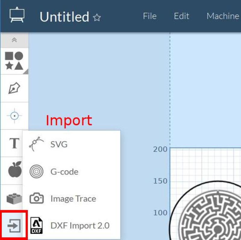
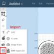 Complex images are easiest to make in CAD or other vector graphics software (e.g. Inkscape), saved as .svg or .dxf and imported into Easel for G-code creation and cutting/engraving. Raster images (.jpg, .png, etc.) need to be converted to vector graphics which can be done using Easel's Image Trace import or other vector graphics software. G-code generated by another CAM program can also be imported.
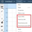
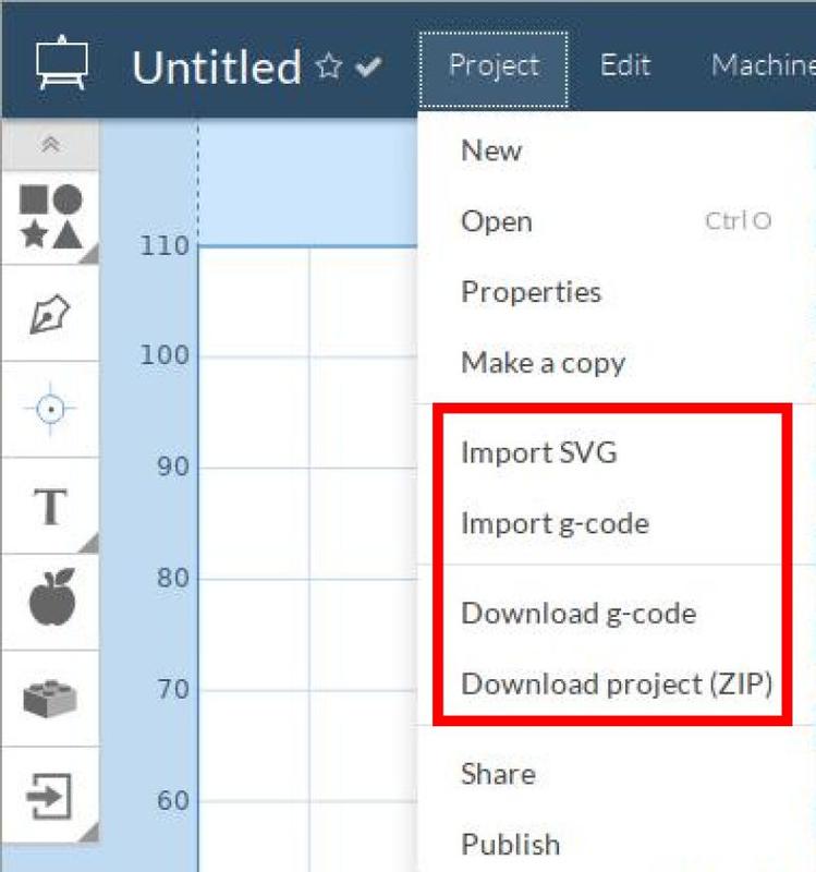
...All import (SVG and G-code) and export (zipped SVG's and G-code) options are now downloadable from the Project menu. While Easel G-code can be run on the Shapeoko, downloading the SVG's and creating the G-code with Estlcam provides numerous advantages (e.g. multi tool, single file projects).
[ comment | link | top ]
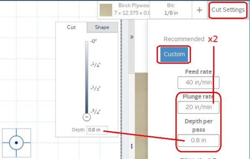
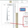 Drilling holes using the hole tool, or the convert to drill holes app, is done with an 1/8" shank circuit board drill, the router speed set to 1, and the pictured custom cut settings. Do not use a router bit or a regular drill bit, only printed circuit board (PCB) drill bits do well at the 16k RPM minimum router speed. While these settings have only been tested on wood, they should work with acrylic as well... Acrylic is less than ideal, accumulated swarf (compressed air can help prevent it) on the bit will lead to melting unless the machine is paused and the swarf removed.
The Plunge rate should be at least 2x (...3x works well in softwood) the Recommended Plunge rate and the Depth per pass should be the same as the Cut Depth. Without these settings the bit will not move smoothly or fast enough (i.e. will get hot and burn/melt the material).
...For an 1/8" drill bit and a lot of 3/8" deep holes (e.g. cribbage boards) even a 700mm/28ipm plunge rate may be a bit slow (a hint of burning). A two plunge setup might be a good idea, e.g. 5mm/.2in depth per pass (two plunges for 3/8" deep holes). In any case, depth per pass should not exceed drill bit flute length.
For through holes, increase the material thickness so that the Cut Depth and Depth per pass can be large enough for the body of the drill to make it through (VS just the tip, .8" VS .75" in the example). Note: the CNC does not use the material thickness info, just the depth of cut info.
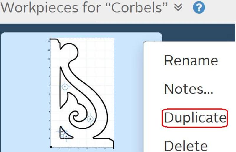
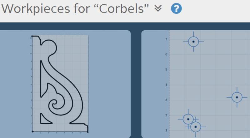
For mixed cut/engrave/drill, create a duplicate workpiece so that the drilling is on a seperate workpiece.
[ comment | link | top ]
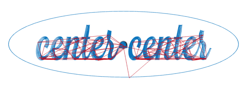
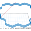 Polylines (12min) cut cleaner and faster than segmented lines (32min). In Easel, the only way to cut inside or outside of the line is with closed polylines. Polylines show up as an unbroken path when Simulate is clicked in Easel. Hidding the material and tilting the preview should show a single vertical start/finish line.
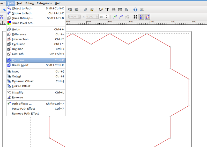
While Inkscape has a Path Combine/Break Apart that looks like it works, and that I thought had worked for me in the past, nothing I tried in Inkscape got me an unbroken path in Easel... The DXF Segmented Line Fix in Inkscape video shows a couple of ways to fix/join segmented lines. The shift-select adjacent segment, box/select node, shift-J to join method may simpler to do in CAD (e.g. clicking adjacent segments can fix or join them, depending on the tool selected).
Another solution, in this case, is to open the dxf or svg in (the free version of) QCAD, add a layer and use the polyline tool to rebuild the shape as a closed polyline. Delete the layer 0 shape, save and import into Easel. For shapes with curves, I use an old CAD program (AutoSketch 9) to join the segments into a polyline (save as dxf and import into Easel). Apparently QCAD can do this, but not with the free version.
[ comment | link | top ]
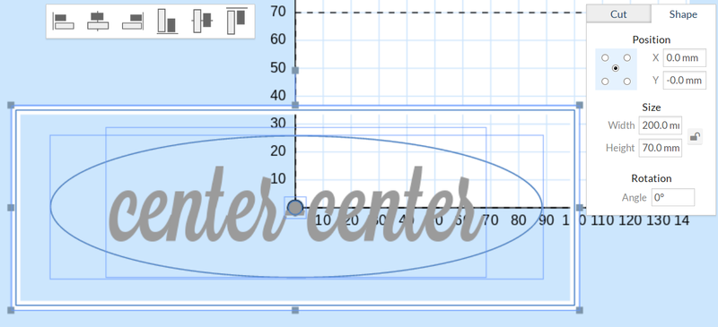
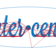 The default Easel origin is the bottom left of the material. Centering any multiple object drawing on the material can be a PITA, especially when text is involved. While using a center origin is not visually intuitive, it is relatively easy to setup. The easiest way is to select all the objects in the drawing (Ctrl A), select the Shape tab, click the center circle and enter 0/0 for X/Y. While this works in simple cases, it is not very precise (center circle and origin are not aligned) and probably won't work as expected when text is involved.
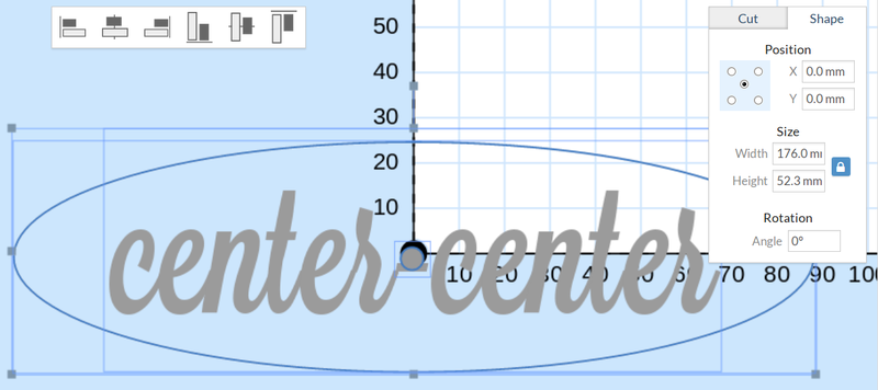
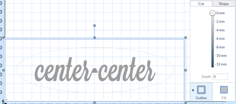
The problem with text is that it doesn't center (its bounding box does) or center isn't the best place for it. For precise center origin alignment of text, or any set of objects: add a square to the drawing, set Cut to Outline and Depth to 0, set Shape to a Size that's bigger than all bounding boxes (blue lines), e.g. material size (if that's big enough). Use Edit > Center to Material to center it on the drawing, select all objects and (as above) set Shape position to 0/0 (center circle selected). While the added perimeter shape shows up in the drawing, the depth was set to 0 so it won't be cut/visible in the preview/simulation (deleting it is optional).
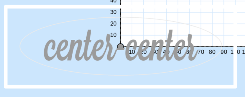
Mark the center of the material with a pencil, align the router bit over the mark and hit carve. Center origin is also handy if you want a reference point that can be used on both the X-Carve and the laser, e.g. route paths/pockets and then laser cut and/or engrave the part (or vice versa). If one or the other operation will cut away the pencil mark, do that one last. While the laser default origin is the top left, it has a center-center option.
Note: the only reason for work area and material dimensions is for visualization and to insure everything will fit. The only information sent to the X-Carve is how and where it should move the router (example image). When designing stuff in Easel, reducing the Machine Work Area dimensions to match the material dimensions will make previews and simulations easier to see (set to 1x1mm for the example image).
[ comment | link | top ]
Easel
Importing and Exporting
 Complex images are easiest to make in CAD or other vector graphics software (e.g. Inkscape), saved as .svg or .dxf and imported into Easel for G-code creation and cutting/engraving. Raster images (.jpg, .png, etc.) need to be converted to vector graphics which can be done using Easel's Image Trace import or other vector graphics software. G-code generated by another CAM program can also be imported.
...All import (SVG and G-code) and export (zipped SVG's and G-code) options are now downloadable from the Project menu. While Easel G-code can be run on the Shapeoko, downloading the SVG's and creating the G-code with Estlcam provides numerous advantages (e.g. multi tool, single file projects).
[ comment | link | top ]
Drilling holes
 Drilling holes using the hole tool, or the convert to drill holes app, is done with an 1/8" shank circuit board drill, the router speed set to 1, and the pictured custom cut settings. Do not use a router bit or a regular drill bit, only printed circuit board (PCB) drill bits do well at the 16k RPM minimum router speed. While these settings have only been tested on wood, they should work with acrylic as well... Acrylic is less than ideal, accumulated swarf (compressed air can help prevent it) on the bit will lead to melting unless the machine is paused and the swarf removed.
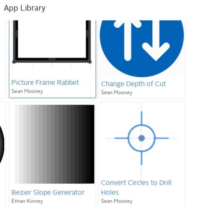
The Plunge rate should be at least 2x (...3x works well in softwood) the Recommended Plunge rate and the Depth per pass should be the same as the Cut Depth. Without these settings the bit will not move smoothly or fast enough (i.e. will get hot and burn/melt the material).
...For an 1/8" drill bit and a lot of 3/8" deep holes (e.g. cribbage boards) even a 700mm/28ipm plunge rate may be a bit slow (a hint of burning). A two plunge setup might be a good idea, e.g. 5mm/.2in depth per pass (two plunges for 3/8" deep holes). In any case, depth per pass should not exceed drill bit flute length.
For through holes, increase the material thickness so that the Cut Depth and Depth per pass can be large enough for the body of the drill to make it through (VS just the tip, .8" VS .75" in the example). Note: the CNC does not use the material thickness info, just the depth of cut info.
For mixed cut/engrave/drill, create a duplicate workpiece so that the drilling is on a seperate workpiece.
[ comment | link | top ]
Polylines
 Polylines (12min) cut cleaner and faster than segmented lines (32min). In Easel, the only way to cut inside or outside of the line is with closed polylines. Polylines show up as an unbroken path when Simulate is clicked in Easel. Hidding the material and tilting the preview should show a single vertical start/finish line.
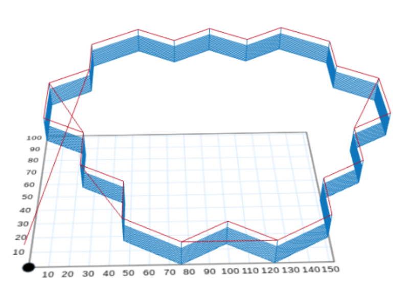
While Inkscape has a Path Combine/Break Apart that looks like it works, and that I thought had worked for me in the past, nothing I tried in Inkscape got me an unbroken path in Easel... The DXF Segmented Line Fix in Inkscape video shows a couple of ways to fix/join segmented lines. The shift-select adjacent segment, box/select node, shift-J to join method may simpler to do in CAD (e.g. clicking adjacent segments can fix or join them, depending on the tool selected).
Another solution, in this case, is to open the dxf or svg in (the free version of) QCAD, add a layer and use the polyline tool to rebuild the shape as a closed polyline. Delete the layer 0 shape, save and import into Easel. For shapes with curves, I use an old CAD program (AutoSketch 9) to join the segments into a polyline (save as dxf and import into Easel). Apparently QCAD can do this, but not with the free version.
[ comment | link | top ]
Center Origin
 The default Easel origin is the bottom left of the material. Centering any multiple object drawing on the material can be a PITA, especially when text is involved. While using a center origin is not visually intuitive, it is relatively easy to setup. The easiest way is to select all the objects in the drawing (Ctrl A), select the Shape tab, click the center circle and enter 0/0 for X/Y. While this works in simple cases, it is not very precise (center circle and origin are not aligned) and probably won't work as expected when text is involved.
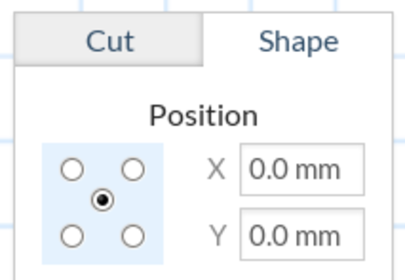
The problem with text is that it doesn't center (its bounding box does) or center isn't the best place for it. For precise center origin alignment of text, or any set of objects: add a square to the drawing, set Cut to Outline and Depth to 0, set Shape to a Size that's bigger than all bounding boxes (blue lines), e.g. material size (if that's big enough). Use Edit > Center to Material to center it on the drawing, select all objects and (as above) set Shape position to 0/0 (center circle selected). While the added perimeter shape shows up in the drawing, the depth was set to 0 so it won't be cut/visible in the preview/simulation (deleting it is optional).
Mark the center of the material with a pencil, align the router bit over the mark and hit carve. Center origin is also handy if you want a reference point that can be used on both the X-Carve and the laser, e.g. route paths/pockets and then laser cut and/or engrave the part (or vice versa). If one or the other operation will cut away the pencil mark, do that one last. While the laser default origin is the top left, it has a center-center option.
Note: the only reason for work area and material dimensions is for visualization and to insure everything will fit. The only information sent to the X-Carve is how and where it should move the router (example image). When designing stuff in Easel, reducing the Machine Work Area dimensions to match the material dimensions will make previews and simulations easier to see (set to 1x1mm for the example image).
[ comment | link | top ]